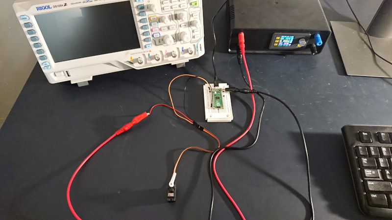
I've used a Raspberry Pi Pico to control a cheap GoTeck GS-9025MG servo. This post details how the Pico's pulse width modulation (PWM) hardware can be used to generate control signals.
The servo datasheet outlines key parameters:
| Dead bandwidth | 7 µsec |
| Neutral position | 1500 µsec |
| Positive pulse travel | 1500 to 1900 µsec |
| Speed | 0.12 sec / 60 deg at no load, 4.8V |
The datasheet does not specify how often the control pulse must be repeated. Wikipedia claims pulse repetition rates of 5 to 25 msec typically work for RC servos. My implementation refreshes every 8 to 9 msec.
Here is the main chunk of code:
    // GoTeck GS-9025MG: neutral at 1500 usec, dead bandwidth of 7 usec
    int min_pwm_usec = 1000;
    int max_pwm_usec = 2000;
    int step_usec = 20;
    int cur_pwm_usec = min_pwm_usec;

    // setup signal pin for PWM
    gpio_set_function(SIGNAL_PIN, GPIO_FUNC_PWM);
    uint slice_num = pwm_gpio_to_slice_num(SIGNAL_PIN);

    // loop cur_pwm_usec cycles high out of 10K
    pwm_set_wrap(slice_num, 10000);
    pwm_set_chan_level(slice_num, PWM_CHAN_A, cur_pwm_usec);

    // clock divide so PWM processed at 1 MHz = 1 usec per cycle
    float div = clock_get_hz(clk_sys) / 1000000;
    pwm_set_clkdiv(slice_num, div);

    // start PWM and wait for servo to reach initial position
    pwm_set_enabled(slice_num, true);
    sleep_ms(250);
First I specify the min, max, and step parameters based on the GoTeck
datasheet. I discovered that 1000 to 2000 µsec provides a larger range of
travel than the specified 1100 to 1900 µsec. My smallest step size is
step_usec, which is generously larger than the 7 µsec dead
bandwidth.
I indicate that SIGNAL_PIN (GPIO 0) should use the Pico's
hardware PWM support:
    gpio_set_function(SIGNAL_PIN, GPIO_FUNC_PWM);
    uint slice_num = pwm_gpio_to_slice_num(SIGNAL_PIN);
Three main parameters control the Pico's PWM signals:
- Number of cycles before the pattern repeats. (
pwm_set_wrap) - How many cycles should have a high signal. (
pwm_set_chan_level) - How PWM cycles relate to the system clock. (
pwm_set_clkdiv)
My code divides the system clock so the PWM hardware operates at 1 MHz, meaning each cycle represents 1 µsec. The PWM pattern repeats every 10,000 cycles. The high signal controls pulse width and thus sets the servo's position. The remainder of the 10,000 cycles are the idle time until the next repetition.
    // loop cur_pwm_usec cycles high out of 10K
    pwm_set_wrap(slice_num, 10000);
    pwm_set_chan_level(slice_num, PWM_CHAN_A, cur_pwm_usec);

    // clock divide so PWM processed at 1 MHz = 1 usec per cycle
    float div = clock_get_hz(clk_sys) / 1000000;
    pwm_set_clkdiv(slice_num, div);
After activating the PWM signal, a sleep allows the servo to move to the desired start position. The duration of the sleep (250 msec) was picked by generously padding the servo's specified speed of 120 msec per 60 degrees.
    pwm_set_enabled(slice_num, true);
    sleep_ms(250);
Now we can position the servo as desired by updating the high cycle count. For example, we move to the middle position with a pulse width of 1500 µsec:
pwm_set_chan_level(slice_num, PWM_CHAN_A, 1500);
The GoTeck servo operates smoothly using the Pico's PWM support. It's easy to verify the control pulse shape using an oscilloscope:
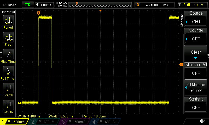
I'm an amateur with microcontrollers and servos. I would be unsurprised to learn that this setup is silly. Still, this experiment was a lot of fun.